What is Magnetic Resonance Imaging?
Magnetic Resonance Imaging (MRI) allows for visualization of internal structures using a strong magnet, radiofrequency, and the properties of the human body to create an image. MRI does not use x-rays or ionizing radiation. Compared to obtaining a radiograph, MRI exams are more costly and require more time.
MRI starts with a strong magnet. The magnetic field is always “on” inside the scan room. Before entering the room, patients are screened for safety.
Once the patient enters the MRI room, they are positioned on the table. The part of interest has to be at the center of the magnet.
To make an image, MRI utilizes the abundance of hydrogen in the body.
When the knee is placed into the MRI scanner, the magnetic fields of hydrogen in the knee are, in a sense, set to a baseline.
Resonance occurs when the technologist adjusts factors on the scanner so that energy is given to the hydrogen magnetic fields. The energy level necessary to give hydrogen energy occurs on the electromagnetic spectrum in the range of radiofrequency (RF).
When the radiofrequency is turned off, hydrogen releases the energy. This release of energy is called signal. Hydrogen on a water molecule and hydrogen on a fat molecule will release this energy at different rates. Fat and water have a different signal intensity. This difference in signal is analyzed to create the MR image.
Soft tissue in the human body (muscles, fat, ligaments, tendons, fluid, etc.) contains an abundance of water and fat molecules. Because of this composition, MRI is an excellent modality for visualizing soft tissue.
MRI starts with a strong magnet. The magnetic field is always “on” inside the scan room. Before entering the room, patients are screened for safety.
- A technologist would have the patient remove all items from his/her person--wallet, cell phone, bobby pins, etc. The technologist may have the patient change into a gown or shorts depending on the clinical site.
- The patient completes a questionnaire to ensure it is safe for them to be in the magnetic field. Some metal implants are safe in the field and some are not safe.
- The technologist goes through extensive training and has resources to consult regarding the safety of implants. The patient’s safety is a primary focus of the MRI technologist. It is important for the patient to tell the technologist of any implants and surgeries so that he/she can ensure patient safety.
Once the patient enters the MRI room, they are positioned on the table. The part of interest has to be at the center of the magnet.
To make an image, MRI utilizes the abundance of hydrogen in the body.
- Hydrogen is an atom that is part of the water molecule and part of the fat molecule.
- The hydrogen atom has one proton (positive charge), one neutron, and one electron (negative charge).
- Because of the structure of hydrogen, the atom actually has a little magnetic field of its own.
When the knee is placed into the MRI scanner, the magnetic fields of hydrogen in the knee are, in a sense, set to a baseline.
Resonance occurs when the technologist adjusts factors on the scanner so that energy is given to the hydrogen magnetic fields. The energy level necessary to give hydrogen energy occurs on the electromagnetic spectrum in the range of radiofrequency (RF).
When the radiofrequency is turned off, hydrogen releases the energy. This release of energy is called signal. Hydrogen on a water molecule and hydrogen on a fat molecule will release this energy at different rates. Fat and water have a different signal intensity. This difference in signal is analyzed to create the MR image.
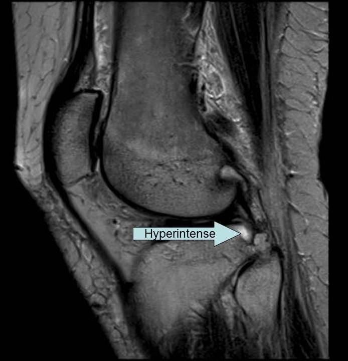
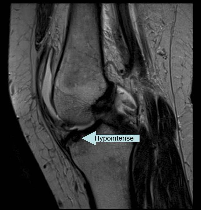
- Areas of high signal on an MRI are bright and appear whiter on the gray scale. The term for bright areas on an MRI is hyperintense.
- Areas of low signal on an MRI are dark and appear blacker on the gray scale. The term for dark areas on an MRI is hypointense.
Soft tissue in the human body (muscles, fat, ligaments, tendons, fluid, etc.) contains an abundance of water and fat molecules. Because of this composition, MRI is an excellent modality for visualizing soft tissue.
|
|
The Normal Knee MRI
Now, you will learn about the appearance of a normal knee MRI. The purpose of this section is to give you a basic introduction. From this module, you will not be able to diagnose or interpret images, but you will have a better sense of the necessity of magnetic resonance to evaluate common knee injuries.
When a patient goes to the MRI department for an exam of his/her knee, several series of the knee are included in the protocol to show all of the necessary information--similar to how several x-rays make a radiography protocol. There are many factors that the technologist can adjust to measure different types of energy given by the hydrogen magnetic fields after resonance. These factors can be altered to create many ways of viewing the knee.
One MRI exam will have three to five series of the knee. Each series has many images. It is similar to slicing a loaf of bread. Several bread slices make the whole loaf. In MRI, the scanner can make image “slices” in any anatomical plane--coronal (front to back), sagittal (side to side), and axial (bottom to top). A knee MRI exam protocol usually has at least one series in each plane.
Other series will be included in the protocol in which the technologist has altered the factors to emphasize different signals from hydrogen. Some series are better for visualizing anatomy (called T1 images), and some are better for visualizing pathology (called T2 images).
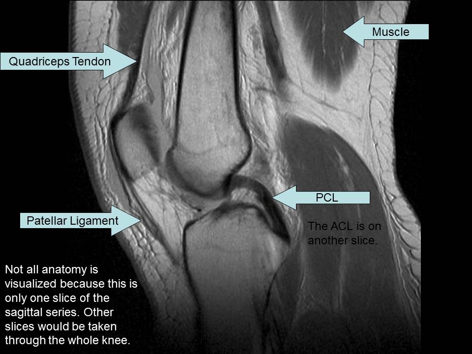
Being able to see soft tissue structures is one benefit of MRI. The sagittal series shows slices of the knee anatomy from side to side. This series is useful to visualize:
|
|

|
The Normal Knee MRI - Coronal
The coronal series shows slices of the knee anatomy from back to front. This series is useful to visualize:
|
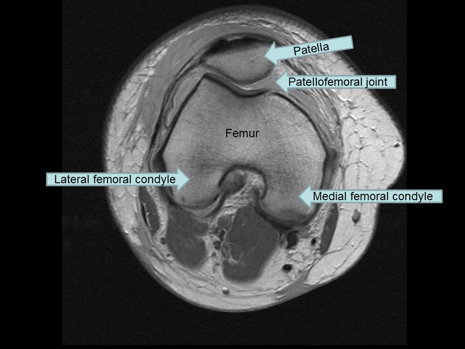
The axial series shows slices of knee anatomy from bottom to top. This series is useful to visualize:
|
|
Knee MRIs and Common Running Injuries
MRI is useful to evaluate several common running injuries about which you have learned in this module. You will have the opportunity to review example cases of a medial collateral ligament tear, a meniscus tear, bursitis, stress fracture confirmation, and chondromalacia.
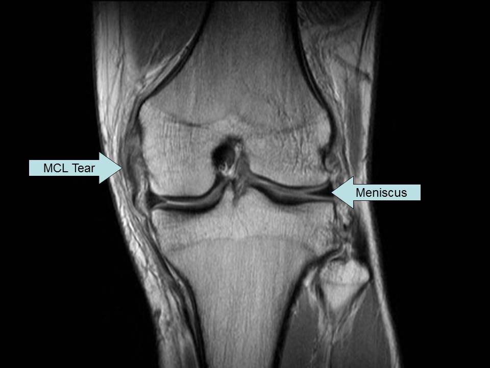
In the first case, you will see a coronal MRI image of the knee. The collateral ligaments connect the joint on the medial and lateral sides. In the example image, the MCL is not contiguous along its length. It is torn. MRI’s ability to show soft tissue allows you to see the ligaments and injuries to them.
|
|

|
In the next example case, you will see a sagittal MRI image of the knee. The slice shown is through the meniscus in question. On this image, the meniscus is a hypointense wedge that gives padding to the joint. The part of the meniscus shown is posterior (at the back of the joint) between the femoral condyle and tibia plateau. A radiologist can tell that this meniscus is torn because of the line inside the meniscus that is a different intensity. A normal meniscus should have the same signal throughout.
|
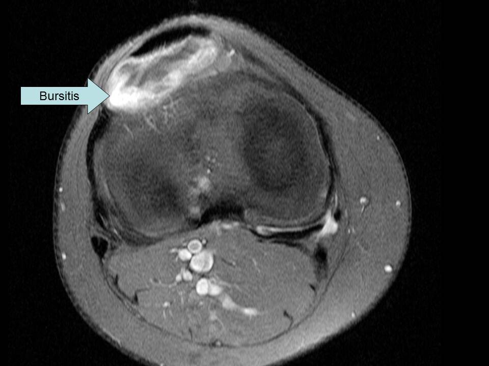
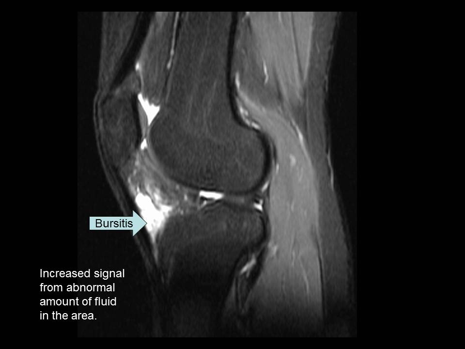
MRI Case Study #3: Bursitis
Your next example case has two images from the same patient--an axial and a sagittal. As you have previously learned, bursitis is inflammation of the bursa. On this MRI, there is hyperintensity behind the patellar ligament which is a result of the patient’s bursitis. There is more fluid in the area than usual causing the increased signal.
|
|
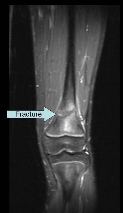
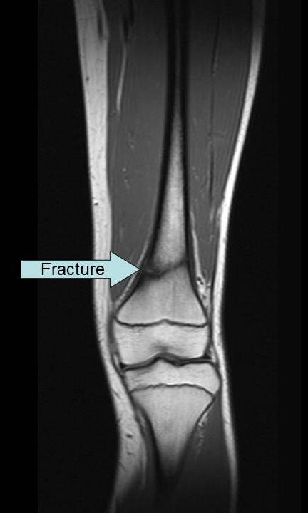
MRI Case Study #4: Confirmation of Stress Fracture
The next MRI case has two coronal images from the same patient as the first radiographic stress fracture example. As a reminder, that patient had a stress/fatigue fracture in the distal femur. On the MRI images, the fracture is evident by the horizontal line through the bone on the shown slice.
|
|
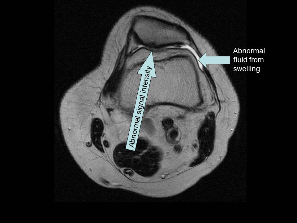
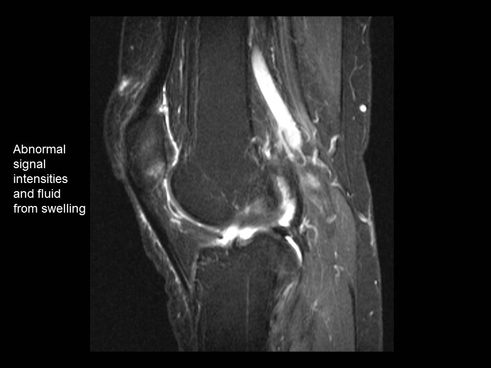
MRI Case Study #5: Chondromalacia
The final MRI case for review is a patient with chondromalacia. Two images are shown from the same patient--an axial and a sagittal. As you learned earlier, chondromalacia is damage to the cartilage behind the patella. Chondromalacia is detected by the radiologist because of abnormal signal intensities and focal swelling behind the patella.
|
|
In summary, you have learned basic information about radiography and magnetic resonance imaging. From this section, you can see that these imaging modalities are helpful in the evaluation of common running injuries. You have an idea of what these exams evaluate in the knee and have reviewed sample cases of various injuries.
For review, take the MRI self-check to the right.
|
References
1. Radiographs and MRI Images: Permission to use these images has been granted to Melissa Culp by Jordan Renner, MD and the Division of Radiologic Science at UNC-Chapel Hill. These images are to be used for this instructional module only and are not to be reproduced.
2. Imaging Content written by: Melissa Culp, BS, RT(R)(MR)
Additional Resources
1. Frank ED, Long BW, Smith BJ, eds. Merrill’s Atlas of Radiographic Positioning and
Procedures. 12 ed. St. Louis, MO: Elsevier; 2012.
2. Kelley LL, Petersen CM, eds. Sectional Anatomy for Imaging Professionals. 3rd ed. St. Louis, MO: Elsevier; 2013.
3. Westbrook C, Roth CK, Talbot J, eds. MRI in Practice. 4th ed. Chichester, West Sussex, UK: Wiley-Blackwell; 2011.